U-BLOX NINA B302 LENDO BATIMENTO CARDÍACO E MANDANDO VIA BLE (ADVERSTISING)

O objetivo deste BLOG é mostrar um exemplo em ARDUINO (NRF52 ADAFRUIT) que permite o NINA B302 se comunicar com o MAX30100 via I2C e disponibilizar o batimento cardíaco via BLE ( BROADCASTING), bem como entrar em LOW ENERGY para economia de bateria, chegando em 600uA.

+

Sensor de Batimento Cardíaco e Oxímetro MAX30100
O Sensor de Batimento Cardíaco e Oxímetro MAX30100 é um módulo composto por 2 LEDs, um fotodetector e circuitos que detectam batimentos cardíacos e medem indiretamente a quantidade de oxigênio no sangue. O sensor é indicado para projetos na área médica, fitness e wearables, entre outros.
O módulo utiliza comunicação I2C e opera na faixa de tensão entre 1.8 e 3.3VDC com um baixíssimo consumo de corrente em modo de espera, permitindo que se mantenha conectado à fontes de energia (como baterias) por longos períodos.
O sensor de batimento cardíaco e oxímetro MAX30100 I2C é indicado para projetos na área médica, fitness e wearables, entre outros.
Especificações:
– Sensor MAX30100 (datasheet)
– Tensão de operação: 1.8 a 3.3V DC
– Interface de comunicação I2C
– Leds integrados ao sensor
– Fotodetector embutido
– Baixo consumo de corrente
– Sistema de cancelamento de luz ambiente integrado
– Elevada capacidade de taxa de amostragem
– Baixo tempo de resposta
– Dimensões: 19 x 14 x 3mm

Adquirimos então os seguintes componentes


-Botão de RESET;
-Botão de Modo BOOTLOADER (W102/W106);
-Plugável no PROTOBOARD;
-Acesso às várias GPIOS;
Pequena

Instalando Arduino Adafruit no NINA B302
Abaixo o roteiro para você seguir:
Baixe e instale o Arduino IDE
Inicie o Arduino IDE, vá em Preferências e adicione
https://www.adafruit.com/package_adafruit_index.json
Baixe e instale o Arduino IDE
Inicie o Arduino IDE, vá em Preferências e adicione
https://www.adafruit.com/package_adafruit_index.json

com "URL adicional do gerenciador de pastas"
Abra o Boards Manager no menu Tools -> Board e instale o "Adafruit nRF52 by Adafruit"
Selecione sua placa nRF5 no menu Ferramentas -> Placa
Adafruit Bluefruit nRF52 Feather
Abra o Boards Manager no menu Tools -> Board e instale o "Adafruit nRF52 by Adafruit"
Selecione sua placa nRF5 no menu Ferramentas -> Placa
Adafruit Bluefruit nRF52 Feather

OBSERVAÇÃO: Durante a instalação, o Arduino IDE leva alguns minutos para extrair as ferramentas após o download, por favor, seja paciente
Use o gravador SEGGER JLINK para gravar o BREAKOUT com módulo NINA B302, conecte nos pinos do SWCLK (pino 7) e SWDIO (pino 9) do SEGGER JLINK nos pinos SWDCLK e SWDIO do BREAKOUT (pinos nas laterais, próximo à antena). Não esquecer de ligar os GND do BREAKOUT no GND do SEGGER JTAG, bem como alimentar o BREAKOUT com 3.3V.

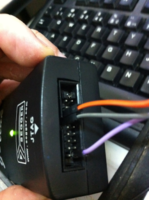
Ligue os pinos SWD DIO e CLK ...

...nestes pinos da placa BREAKOUT

Você pode também usar o ST-LINK V2

Abra J-FLASH lite e grave o bootloader da Adafruit

C:\Users\xxxxx\AppData\Local\Arduino15\packages\adafruit\hardware\nrf52\1.3.0\bootloader
Com ele, você poderá transferir programas via DFU USB. Maiores detalhes sobre este bootloader
https://learn.adafruit.com/introducing-the-adafruit-nrf52840-feather/update-bootloader
ATENÇÃO, o bootloader utiliza a USB para gravação do NINA 302, OU SEJA, CRIA UMA COMM VIRTUAL, TAMBÉM PARA SER A SERIAL PADRÃO DO ARDUINO
https://github.com/adafruit/Adafruit_Windows_Drivers
Conecte na USB + e USB - um cabo USB, AGUARDE INSTALAR OS DRIVERS

CONEXÃO COM MAX30100 VIA I2C E EXECUÇÃO DO PROGRAMA
Observações importantes:
- Para estabelecer a comunicação com o MAX30100, o mesmo foi conectado nos pinos IOS 32 e 46 do U-BLOX NINA B302.
Como referência foi aberto o arquivo variant.cpp do feather_nrf52840_express para identificar quais GPIOS são utilizados para I2C.
.
.
.
// D22 .. D23 (aka I2C pins)
12, // D22 is P0.12 (SDA)
11, // D23 is P0.11 (SCL)
.
.
.
Nele mostra que os pinos escolhidos para I2C são P0.12 e P0.11 (SDA e SCL), ao verificar no datasheet do U-BLOX NINA B302, está descrito que os pinos correspondem aos IOS do módulo 32 e 46.

- O módulo MAX30100 tem PULLUPS para o I2C ligados em 1.8V, você terá que remover os resistores.

- Ao conectar o módulo MAX30100 no U-BLOX NINA B302, coloque resistores PULLUP de 75K para 3.3V no I2C.

Código final
#if defined ARDUINO_NRF52840_CIRCUITPLAY
#define PIN_VBAT A8 // this is just a mock read, we'll use the light sensor, so we can run the test
#endif
uint32_t vbat_pin = PIN_VBAT; // A7 for feather nRF52832, A6 for nRF52840
#define VBAT_MV_PER_LSB (0.73242188F) // 3.0V ADC range and 12-bit ADC resolution = 3000mV/4096
#ifdef NRF52840_XXAA
#define VBAT_DIVIDER (0.5F) // 150K + 150K voltage divider on VBAT
#define VBAT_DIVIDER_COMP (2.0F) // Compensation factor for the VBAT divider
#else
#define VBAT_DIVIDER (0.71275837F) // 2M + 0.806M voltage divider on VBAT = (2M / (0.806M + 2M))
#define VBAT_DIVIDER_COMP (1.403F) // Compensation factor for the VBAT divider
#endif
#define REAL_VBAT_MV_PER_LSB (VBAT_DIVIDER_COMP * VBAT_MV_PER_LSB)
float readVBAT(void) {
float raw;
// Set the analog reference to 3.0V (default = 3.6V)
analogReference(AR_INTERNAL_3_0);
// Set the resolution to 12-bit (0..4095)
analogReadResolution(12); // Can be 8, 10, 12 or 14
// Let the ADC settle
delay(1);
// Get the raw 12-bit, 0..3000mV ADC value
raw = analogRead(vbat_pin);
// Set the ADC back to the default settings
analogReference(AR_DEFAULT);
analogReadResolution(10);
// Convert the raw value to compensated mv, taking the resistor-
// divider into account (providing the actual LIPO voltage)
// ADC range is 0..3000mV and resolution is 12-bit (0..4095)
return raw * REAL_VBAT_MV_PER_LSB;
}
uint8_t mvToPercent(float mvolts) {
if(mvolts<3300)
return 0;
if(mvolts <3600) {
mvolts -= 3300;
return mvolts/30;
}
mvolts -= 3600;
return 10 + (mvolts * 0.15F ); // thats mvolts /6.66666666
}
#include <Wire.h>
#include "MAX30100_PulseOximeter.h"
#include "MAX30100.h"
#define REPORTING_PERIOD_MS 20000
// PulseOximeter is the higher level interface to the sensor
// it offers:
// * beat detection reporting
// * heart rate calculation
// * SpO2 (oxidation level) calculation
PulseOximeter pox;
MAX30100 sensor;
uint32_t tsLastReport = 0;
float HeartRate_var;
int8_t SpO2_var;
float Temp;
#include "bluefruit.h"
// Device Name: Maximum 30 bytes
#define DEVICE_NAME "MAX30100 - nRF52"
typedef struct {
uint8_t id[2]; // maker_id は 0xffff に固定
uint16_t pid; // 送信側の識別用
uint8_t HeartRate_int;
uint8_t HeartRate_float;
uint8_t SpO2;
uint8_t Vbat_int;
uint8_t Vbat_float;
uint8_t Vbat_Perc;
} adv_data_t;
adv_data_t adv_data = {
.id = {0xff, 0xff},
.pid = 0x3412,
.HeartRate_int = 0,
.HeartRate_float = 0,
.SpO2 = 0,
.Vbat_int = 0,
.Vbat_float = 0,
.Vbat_Perc = 0,
};
void adv_temp() {
Bluefruit.Advertising.clearData();
adv_data.HeartRate_int = (uint8_t) HeartRate_var;
adv_data.HeartRate_float = (uint8_t)((((float) HeartRate_var - (uint8_t) HeartRate_var))*100.0);
adv_data.SpO2 = SpO2_var;
// Get a raw ADC reading
float vbat_mv = readVBAT();
// Convert from raw mv to percentage (based on LIPO chemistry)
uint8_t vbat_per = mvToPercent(vbat_mv);
adv_data.Vbat_int = (uint8_t) vbat_mv;
adv_data.Vbat_float = (uint8_t)((((float) vbat_mv - (uint8_t) vbat_mv))*100.0);
adv_data.Vbat_Perc = mvToPercent(vbat_mv);
Bluefruit.Advertising.addData(BLE_GAP_AD_TYPE_MANUFACTURER_SPECIFIC_DATA, &adv_data, sizeof(adv_data));
Bluefruit.Advertising.start(5); //
}
// Callback (registered below) fired when a pulse is detected
void onBeatDetected()
{
Serial.println("Beat!");
}
void setup() {
Serial.begin(9600);
Bluefruit.begin();
Bluefruit.setName(DEVICE_NAME);
Bluefruit.autoConnLed(false);
Bluefruit.setTxPower(0); // Check bluefruit.h for supported values
Bluefruit.Advertising.addFlags(BLE_GAP_ADV_FLAGS_LE_ONLY_GENERAL_DISC_MODE);
Bluefruit.Advertising.setType(BLE_GAP_ADV_TYPE_NONCONNECTABLE_NONSCANNABLE_UNDIRECTED);
Bluefruit.Advertising.addData(BLE_GAP_AD_TYPE_MANUFACTURER_SPECIFIC_DATA, &adv_data, sizeof(adv_data));
Bluefruit.Advertising.setIntervalMS(400, 2500); //
Bluefruit.Advertising.setFastTimeout(1);
//NO PULLUPS
pinMode(PIN_WIRE_SDA,INPUT);
pinMode(PIN_WIRE_SCL,INPUT);
// Initialize sensor
if (!pox.begin()) {
while(1)
{
Serial.println("Fail");
delay(1500);
//for(;;);
}
} else {
Serial.println("Success!");
delay(1500);
Serial.println("TUM TUM!");
delay(1500);
}
// The default current for the IR LED is 50mA and it could be changed
// by uncommenting the following line. Check MAX30100_Registers.h for all the
// available options.
//pox.setIRLedCurrent(MAX30100_LED_CURR_7_6MA);
// Register a callback for the beat detection
pox.setOnBeatDetectedCallback(onBeatDetected);
}
void loop() {
// Make sure to call update as fast as possible
pox.update();
// Asynchronously dump heart rate and oxidation levels to the serial
// For both, a value of 0 means "invalid"
if (!(millis() - tsLastReport > REPORTING_PERIOD_MS)) {
//Serial.print("Heart rate:");
HeartRate_var = pox.getHeartRate();
//Serial.print(HeartRate_var = pox.getHeartRate());
//Serial.print("bpm / SpO2:");
SpO2_var = pox.getSpO2();
//Serial.print(SpO2_var = pox.getSpO2());
//Serial.println("%");
adv_temp();
}
else
{
Serial.print("Heart rate:");
Serial.println(HeartRate_var = pox.getHeartRate());
Serial.print("bpm / SpO2:");
Serial.println(SpO2_var = pox.getSpO2());
pox.shutdown();
delay(10000);
pox.resume();
tsLastReport = millis();
}
adv_temp();
}
Compile o programa e transfira para o U-BLOX NINA B302

Como podem observar, o programa será transferido!


Resete o U-BLOX NINA B302, coloque o dedo no sensor e veja a execução
- O programa basicamente coleta dados do MAX30100 e mostra na SERIAL (USB), também entra em LOW ENERGY, por dez segundos através da própria instrução do Arduino delay(10000), caindo drasticamente o consumo. Para reduzir ainda mais o consumo, foi executado a função Arduino do MAX30100 shutdown() bem como desconectado da USB o U-BLOX NINA B302, caindo de 35mA (LEDS do MAX30100) para 600uA. Para também reduzir o consumo, você pode desabilitar a UART ou/e trocar os valores dos resistores PULLUP do I2C.


- Para fazer o Advertising com o BLE, foi criado um registro com os dados que devem ser enviados.
adv_data_t adv_data = {
.id = {0xff, 0xff},
.pid = 0x3412,
.HeartRate_int = 0,
.HeartRate_float = 0,
.SpO2 = 0,
.Vbat_int = 0,
.Vbat_float = 0,
.Vbat_Perc = 0,
};

Atualmente foram implementados no código acima o HeartRate e Sp02, faltando apenas a leitura da tensão da Bateria em um dos ADC do U-BLOX NINA B302.
Dúvidas:
suporte@smartcore.com.br
Referências:
suporte@smartcore.com.br
Referências:
https://okiraku-camera.tokyo/blog/?p=13307
https://makersportal.com/blog/2019/6/24/arduino-heart-rate-monitor-using-max30102-and-pulse-oximetry
Sobre a SMARTCORE
A SmartCore fornece módulos para comunicação wireless, biometria, conectividade, rastreamento e automação.
Nosso portfólio inclui modem 2G/3G/4G/NB-IoT/Cat.M, satelital, módulos WiFi, Bluetooth, GNSS / GPS, Sigfox, LoRa, leitor de cartão, leitor QR code, mecanismo de impressão, mini-board PC, antena, pigtail, LCD, bateria, repetidor GPS e sensores.
Mais detalhes em www.smartcore.com.br
Nenhum comentário:
Postar um comentário